

OEM Lightning Strike Current Sensor Selection Criteria and Key Features
2026-11-16
When sourcing an OEM lightning strike current sensor, the difference between a robust design and a field failure often comes down to a handful of details that don’t make the headline specs. Peak current handling, response linearity, isolation voltage, and mechanical fit all interact in ways that can trip up even experienced engineers. That’s why this guide focuses on the selection criteria and key features that actually matter in practice. Xiasen has built its sensor portfolio around these real-world constraints, and we’ll use that perspective to walk through what to prioritize.
What Really Matters When Picking a Lightning Current Sensor for OEM Builds
Most integrators start by comparing peak current ratings or price, but that misses the real pain points. In an OEM build, a lightning current sensor has to survive repeated 8/20 µs and 10/350 µs surges without losing calibration or picking up stray fields from adjacent busbars. Rogowski coils handle fast di/dt well, yet their integrator circuits drift with temperature unless carefully compensated. Open-loop Hall sensors are tempting for isolation, but they can saturate under extreme pulses and introduce offset errors that confuse downstream protection logic. What actually matters is the sensor's tested response to non-periodic transients, including its shielding effectiveness and how cleanly it interfaces with your grounding scheme.
Packaging often decides whether a sensor is OEM-ready. A design that works on the bench may fail after thermal cycling from -40°C to +85°C, especially if the zero offset moves enough to trigger false events. Look for creepage and clearance distances that meet IEC 61643 or UL 1449 for your target market, and pay attention to connector sealing—moisture ingress is a common field failure. Also, verify that the manufacturer provides real lightning impulse test data, not just a generic datasheet curve, and confirm whether the analog or digital output matches your signal conditioning without adding latency or noise.
Long-term supply stability and field serviceability are rarely discussed but are crucial for OEM builds. If the sensor vendor changes die attach materials or firmware without notice, your calibration could shift silently. A good partner offers version control, end-of-life notifications, and ideally a self-diagnostic output that reports sensor health. This allows your equipment to flag a degrading channel before it fails during an actual storm. In short, the right choice hinges on how the sensor behaves inside your enclosure under real fault conditions, not on the headline specifications alone.
Beyond the Spec Sheet: Sensor Features That Survive Real Strikes
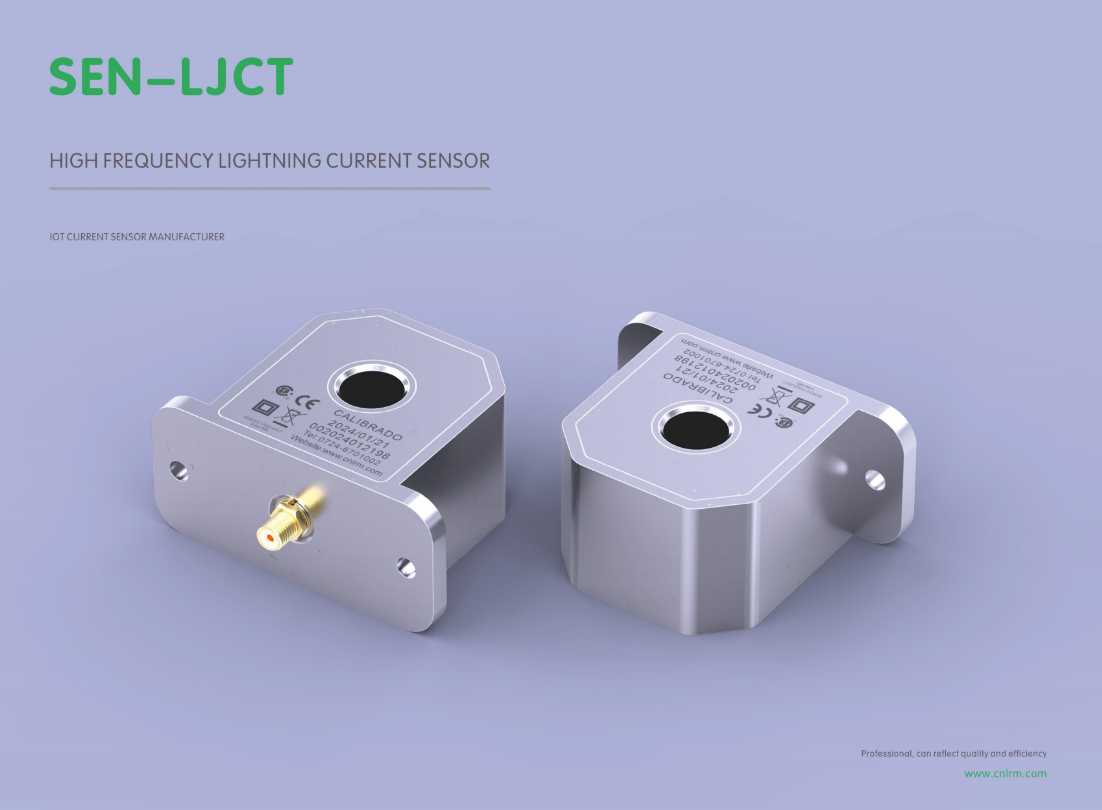
Most sensor datasheets lead with resolution and response time, but those numbers rarely matter when a forklift backs into a conveyor or a wrench slips off a bolt. Real strikes test the stuff that never shows up in a bullet-point list: the way an epoxy fillet absorbs shock along the housing edge, the slight inboard set of the lens so it takes a glancing hit instead of a direct one, or the extra wrap of shield that keeps a cut cable from turning into a dead zone mid-shift.
The sensors that keep running after a hard impact tend to share a few unglamorous habits. Their mounting brackets flex a little instead of snapping, their internal boards are potted with a material that stays slightly soft even in cold storage, and their connector threads have enough engagement to hold after the housing gets knocked out of square. You won't see any of that on a spec sheet, but it's the difference between a line that stops for five minutes and one that stops for five hours.
The next time you compare two sensors with identical ranges and switching frequencies, try dropping each one waist-high onto concrete before you sign the PO. The one that survives will have its real feature set written in the scars, not the datasheet.
OEM Integration Pitfalls: Why Some Current Sensors Fail in the Field
Most field failures we trace back to current sensors don’t start with the sensor itself. They start with how it was bolted into the harness. A common one is using a steel mounting bracket that expands at a different rate than the sensor housing. Over a few hundred thermal cycles, the PCB inside flexes just enough to crack a solder joint on the shunt or Hall element. The sensor still powers up on the bench, but in the vehicle it drops out intermittently under load.
Another repeat offender is grounding. Engineers tie the sensor’s analog ground to the chassis at a different point than the ECU ground, and suddenly the 0–5 V output has a few hundred millivolts of offset that drifts with temperature and alternator load. It looks like a noisy sensor, but it’s really a ground loop. Adding a dedicated return wire or moving the ground reference usually clears it up without swapping the part.
Firmware can also do its share of damage. If the ADC samples too slowly or the anti-aliasing filter is sized for a different bandwidth than the sensor’s actual rise time, you get readings that look fine at steady state but miss fast current spikes. Those missed spikes then cause torque ripple or false overcurrent trips once the system is in the field, which is exactly the kind of problem that never shows up on a lab bench.
Matching Sensor Bandwidth to Lightning’s Fastest Pulses Without Overkill
Lightning's most energetic emissions aren't the long, lazy return strokes people picture. The real challenge sits in the submicrosecond range, where narrow bipolar events and stepped leader bursts pack spectral energy well past 10 MHz. A sensor with too narrow a bandwidth, say 1 MHz, will smear these transients into smooth blobs, losing the sharp risetime that distinguishes cloud-to-ground from intracloud activity. But widening the front end recklessly invites a different problem: RF noise from FM broadcast, aeronautical bands, and switch-mode power supplies floods the data stream.
Matching bandwidth to the pulse means choosing a front-end filter that passes the fastest features without amplifying everything above them. Practical lightning sensors often settle around 20–30 MHz for close-range work, enough to catch the 50 ns risetimes of compact intracloud discharges while rolling off before the VHF pager and satellite bands become unmanageable. A well-placed anti-alias filter in the analog chain, paired with a modest sampling rate, can do more for pulse fidelity than an exotic multi-gigahertz digitizer. The goal isn't to capture every nanosecond of electromagnetic chaos; it's to preserve the spectral signature that lets a classifier tell a real lightning pulse from a distant motor brush.
Isolation and Safety: Non-Negotiables for High-Voltage Sensor Design
Working with high-voltage systems leaves no room for compromise when it comes to isolation and safety. A sensor that handles hundreds or thousands of volts must physically separate the measurement circuitry from the dangerous potential, not just with a thin layer of insulation but with certified barriers that withstand transient spikes, partial discharge, and years of thermal cycling. The goal is simple: no path for current to reach a human or a low-voltage control system, even under worst-case fault conditions. That demands careful material selection, creepage and clearance distances that exceed minimum standards, and a layout that anticipates contamination, humidity, and altitude derating.
Many designers focus on the isolation rating printed on a datasheet, but safety in practice depends on how that isolation behaves after hundreds of power cycles, vibration, and exposure to dust or moisture. A high-voltage sensor should include redundant protection—such as reinforced insulation, shielding between primary and secondary, and fail-safe output behavior if the isolation barrier is ever compromised. For example, a current sensor used in an electric vehicle battery pack needs not only galvanic isolation for signal lines but also robust mechanical anchoring so a crash cannot deform the housing and reduce the isolation gap. Testing for partial discharge, dielectric withstand, and impulse voltage becomes a routine part of qualification, not an afterthought.
Beyond component-level isolation, system safety relies on how the sensor communicates and behaves during faults. A well-designed high-voltage sensor clamps its output, triggers a defined error state, or opens a secondary protection loop if the measured voltage or current exceeds safe bounds. This prevents a single point of failure from cascading into a dangerous situation. In industrial motor drives, solar inverters, or medical imaging equipment, that kind of predictable, fail-safe response is what separates a certified design from one that merely survives a bench test. Isolation and safety are not features to be balanced against cost or board space—they define the sensor's entire architecture from the first sketch to the final production test.
Balancing Cost and Longevity in Lightning Strike Monitoring
Lightning monitoring systems often carry a hidden assumption: that more sensors and higher sampling rates automatically deliver better protection. In practice, this approach can exhaust budgets quickly without meaningfully extending the operational life of critical infrastructure. A smarter path begins by mapping the actual density of strike activity across your specific geography. Rather than covering every square kilometer uniformly, you can concentrate spending on zones where lightning poses the greatest threat to power lines, turbines, or communication towers. This risk-weighted placement frequently cuts hardware costs by a third while preserving detection coverage where it matters most.
Longevity depends less on expensive enclosures and more on design choices that respect field conditions. Solar-powered sensors with modest energy budgets tend to fail less often than grid-tied units, especially in remote areas where voltage spikes and outages are common. Choosing components rated for wide temperature swings and high humidity—without overspending on military-grade specs—strikes a practical balance. Simple self-diagnostics that report battery health and sensor drift allow maintenance teams to replace failing parts before they compromise data, avoiding costly emergency callouts that erode the initial savings.
The real lever for cost and lifespan is in the data handling, not the sensor count. Instead of streaming raw waveform data continuously, edge processing can classify each strike and send only compact summaries when a network connection is available. This reduces data transmission costs, extends storage life, and lessens the thermal load on onboard electronics. Periodic firmware updates that optimize detection algorithms can refresh an older network’s capabilities without replacing hardware. When procurement teams ask whether a monitoring system is affordable over ten years—not just at installation—the answer usually lies in such operational economies rather than in chasing the newest sensor generation.
FAQ
Focus on the sensor's ability to capture fast rise times and high peak currents without saturation, while keeping weight and footprint minimal. The output interface also needs to match existing avionics signal conditioning without extra buffering.
Rogowski coils offer galvanic isolation and handle very high di/dt without core saturation, making them ideal for lightning transients. Shunts can work but add insertion loss and require careful thermal management under repeated strikes.
You usually need at least several hundred kilohertz of bandwidth, and the dynamic range should span from a few hundred amps to over 200 kA to capture both induced effects and direct attachment pulses.
Yes. Sensors must be placed away from ferromagnetic materials and high-current return paths that can distort the magnetic field. Also, cable routing and connector strain relief matter for long-term stability.
Wide temperature swings can shift offset and gain in some sensor types. Choosing a design with low temperature coefficient and built-in compensation, or at least a well-characterized drift curve, is critical for reliable post-flight data.
Look for compliance with DO-160G environmental categories and, if it's part of a lightning protection system, acceptance under SAE ARP5412/5414 test practices or equivalent EASA/FAA guidance.
Yes. By capturing waveform parameters like peak current, action integral, and charge transfer, maintenance teams can assess cumulative stress on composite structures and decide on inspection intervals.
It usually involves bench testing with high-current surge generators, comparing against a reference shunt or Pearson coil, followed by flight test or ground strike campaigns to verify the full installation behaves as expected.
Conclusion
The real choice for an OEM lightning current sensor rarely comes down to the headline number on a datasheet. Field failures usually trace back to how the device behaves after repeated surges, not during a single lab pulse. Bandwidth needs to align with the fastest components of a strike—typically the steep rising edge of the first return stroke—but chasing unnecessary megahertz only invites noise and layout headaches. Equally critical is galvanic isolation and creepage design, since the sensor often sits within centimeters of a conductor carrying hundreds of kiloamps. Integration traps include connector mating under thermal shock, shield grounding loops, and mechanical resonance from wind or thunder-induced vibration. If the sensor's mounting or cable routing degrades after the first storm season, no amount of front-end accuracy matters.
Cost and longevity are not opposing forces if the selection focuses on drift, insulation aging, and calibration stability over a decade of exposure. A Rogowski coil may look cheap initially, yet its integrator can drift after multiple high-energy events, while a shunt-based design offers precision but demands bulky isolation. Smart OEMs look beyond unit price to total lifecycle: how many strikes before recalibration, how easily a failed unit is swapped in the field, and whether the vendor has test data for repeated 10/350 µs and 8/20 µs waveforms. The best sensors combine conservative thermal margins, sealed enclosures, and simple analog front ends that survive real-world installation, not just the qualification lab. That balance—not raw specs—is what separates builds that monitor reliably for years from those that silently fail after the first major storm.
Contact Us
Contact Person: Liu Mengyang
Email: [email protected]
Tel/WhatsApp: 8618727589233
Website: https://www.cnlrm.com/en/