

High Quality Phased Array Transducer: Top Considerations for Superior Performance
2026-09-09
A phased array transducer can be the difference between catching a critical flaw and missing it entirely. But “high quality” isn’t just a marketing label—it’s the result of specific engineering choices that affect resolution, sensitivity, and durability. Before you invest, here are the top considerations that separate superior performance from average results, and why Siansonic consistently applies them.
Choosing the Right Piezoelectric Material Isn't Just About k33
The k33 figure dominates datasheets, but fixating on it often blinds engineers to what happens outside the lab. Take underwater transducers: a material with impressive k33 under free boundary conditions can suffer a dramatic drop in effective coupling once encased in a pressure housing and subjected to hydrostatic load. In that scenario, the hydrostatic piezoelectric coefficients dh and gh, along with acoustic impedance matching, become far more decisive than the headline number.
Another overlooked dimension is the mechanical quality factor Qm and dielectric loss. For high-power, narrowband applications like ultrasonic welding or cleaning, a low-Qm material may still boast a decent k33, yet it generates excessive heat and wastes electrical-to-acoustic conversion efficiency. Conversely, in certain wideband sensors, a moderate Qm paired with a lower dielectric constant yields a flatter response—even if the k33 is slightly lower, the system-level performance wins.
Ultimately, engineering choices are never single-parameter optimizations. Temperature stability, aging rate, cost, and batch-to-batch consistency often matter more for product reliability than the paper value of k33. For instance, some lead-free piezoceramics have lower k33 than PZT-5H, but their regulatory compliance and stable dielectric behavior over a wide temperature range make them the smarter pick. Material selection should follow the entire lifecycle, not an isolated coefficient.
Element Geometry and the Battle Against Crosstalk
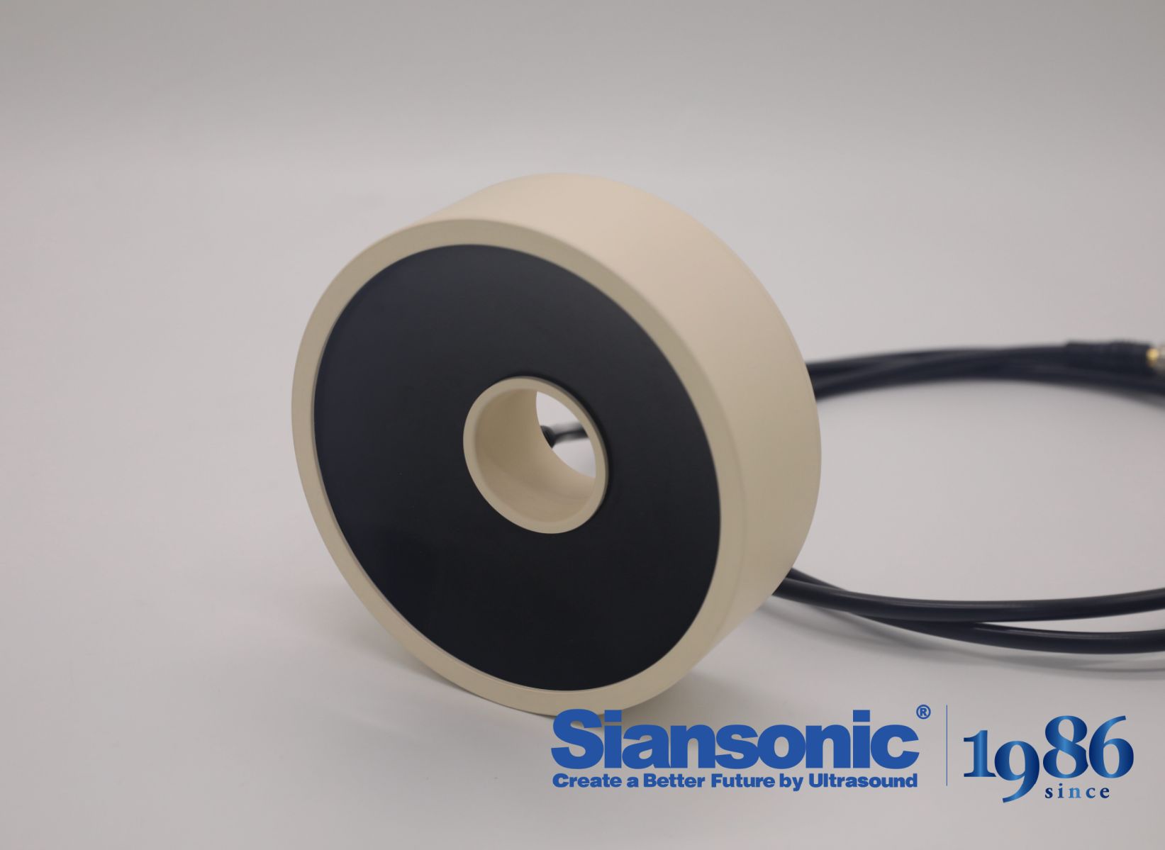
Tightening the spacing between elements usually feels like the obvious way to pack more resolution into a small footprint, but it quietly hands crosstalk an invitation. Once the gaps shrink, the fields that should stay local start leaking sideways, and what reaches the neighboring element isn't signal anymore—it's a distorted echo of the original pulse. Oddly enough, the geometry that seems efficient on paper often creates the worst interference in practice.
A better route is to treat the element's shape as something to negotiate rather than inherit. Tapered edges, asymmetric footprints, or slightly stretched aspect ratios can push the unwanted coupling toward frequencies or directions where it does less harm. The trick is not to eliminate crosstalk entirely, since that's rarely possible, but to reshape where and how it appears so the system can still separate real input from leaked energy. In that sense, geometry becomes less about fitting elements in and more about deciding which compromises are worth living with.
Matching Layer Design: More Than a λ/4 Guess
The quarter-wave transformer often gets treated as the default answer for acoustic matching, but that shorthand misses how much the layer geometry, material choice, and operating bandwidth actually shape performance. A λ/4 layer works beautifully at one frequency, yet real transducers—whether for medical imaging or underwater sonar—must handle pulses with fractional bandwidths of 50% or more. In those cases, the matching layer needs to behave less like a simple impedance inverter and more like a carefully tuned segment of a transmission line, where its characteristic impedance and thickness are selected together to flatten the passband rather than hit a single impedance target.
What separates a thoughtful matching layer design from a rough starting guess is attention to dispersion and attenuation inside the layer itself. Many engineers assume the layer material is lossless and homogeneous, then discover that cured epoxies loaded with tungsten or alumina powder show measurable acoustic loss at high frequencies. That loss can actually be used deliberately—a slightly lossy matching layer can damp out ringing and reduce transducer Q, improving axial resolution without sacrificing too much sensitivity. It is a trade-off that rarely appears in textbook equations but shows up clearly in measured pulse-echo responses.
Multi-layer stacks push the idea further: instead of one λ/4 layer that only matches at a single spot, two or three layers with graded acoustic impedances create a broadband matching network. The design process then resembles filter synthesis more than simple geometry. You choose layer count and impedance ratios to shape the insertion loss curve, then verify with a full-wave model that accounts for shear mode conversion and edge effects. In practice, the best designs start from the λ/4 rule as a first approximation, but they only become reliable after iterative simulation and material characterization—because the real goal is not guessing a thickness, but engineering the entire transmission path for a specific bandwidth and ring-down behavior.
Heat Dissipation Paths That Keep the Array Stable
Thermal stability in a densely packed array depends on how effectively heat leaves each active element. Without well-defined escape routes, localized temperature spikes cause uneven expansion, shifting electrical characteristics and accelerating material fatigue. The most reliable designs treat heat removal as a series of parallel and series paths—each one sized to handle transient overloads without allowing the array to drift outside its safe operating window.
Conduction typically dominates the early stages of heat transfer. Chip-level hot spots feed into copper or aluminum nitride submounts, which spread the thermal load before passing it through a thin layer of indium or graphite-based interface material. This stack lowers contact resistance at every boundary, preventing the formation of hot pockets that would otherwise undermine array alignment. In many high-density layouts, vapor chambers or embedded heat pipes are introduced beneath the substrate to move heat laterally toward the edges, where it can be released more freely.
Once heat reaches the outer surfaces, convection and radiation take over. Fin arrays or microchannel cold plates transfer energy to the surrounding air or liquid coolant, with natural convection sufficing for low-power arrays and forced airflow or pumped liquid required for higher densities. Radiative cooling adds a secondary path, particularly in vacuum-like enclosures or when surface emissivity is boosted through coatings. Keeping these paths unobstructed—free of dust, oxidation, or uneven mounting pressure—is what allows an array to hold its temperature gradient within tight limits and remain stable over long operational runs.
Tolerances That Make or Break Beam Steering
In beam steering, the difference between a crisp, repeatable deflection and a wandering spot often comes down to a handful of machining and assembly tolerances that rarely show up on a top-level spec sheet. Mirror flatness, bearing runout, and the concentricity of rotary stages all accumulate in ways that don't just shift the beam but alter its divergence at the target. A kinematic mount that feels rock-solid on the bench can betray a few microradians of sag once thermal gradients spread through the housing, and that drift is often mistaken for calibration error.
What separates systems that hold their pointing over hours from those that need constant re-zeroing is how tolerance budgets are stacked, not just how tightly individual parts are made. Actuator backlash under load, differential expansion between aluminum and steel components, and even the flatness spec of the mirror under changing ambient pressure create non-linear errors that simple peak-to-valley numbers miss. Designers who treat these as interactive constraints rather than independent checkboxes end up with beam steering that survives field conditions instead of just passing a clean-room acceptance test.
Enough Testing to Catch What Simulations Miss
Simulations are invaluable for stress-testing early designs, but they operate inside a controlled model of reality. The model itself carries assumptions about user behavior, hardware tolerances, and network conditions. When those assumptions drift even slightly from what happens on real devices or in actual workflows, the simulation becomes a polished mirror rather than a reliable predictor. Enough testing—meaning repeated, varied, and often messy attempts to break the product—is what surfaces the gaps that a neat simulation never thinks to imitate.
Real-world testing finds the problems that live between components. A simulation might verify that a database query returns in 200 milliseconds under simulated load, but it cannot easily reproduce the peculiar interaction between a specific mobile browser and a flaky Wi-Fi handoff. Nor does it account for users who double-tap buttons out of impatience or leave an app running in the background for days. These failures are not theoretical; they appear only after a sufficient volume of unscripted test sessions.
The goal is not to abandon simulations but to complement them with a testing effort broad enough to catch what they miss. That means combining automated checks, staged rollouts, and direct observation of real usage. Teams that invest in this kind of layered testing stop being surprised by edge cases after launch—because they have already met enough of those edge cases in test environments that closely mirror the messy, unpredictable world where the product actually has to work.
FAQ
Precision in piezoelectric composite assembly is the biggest factor. Each element must be cut and poled with tight tolerances, and the acoustic stack needs flawless bonding between the crystal, matching layers, and backing. When these details are right, you get consistent sensitivity and predictable beam formation across the entire array.
Higher frequencies offer finer axial and lateral resolution for shallow flaws, while lower frequencies penetrate deeper into attenuating materials. The best transducer isn't the one with the highest number on paper; it's the one whose frequency response aligns with the thickness, grain structure, and defect type you're targeting.
Element count and pitch define how precisely you can steer and focus the acoustic beam. A large aperture with many small elements gives superior focal control and reduces unwanted grating lobes. However, dense element spacing also puts more demand on the cable and connector, so mechanical design has to keep up.
Matching layers bridge the huge acoustic impedance gap between the ceramic and the test piece, maximizing energy transfer. The backing, on the other hand, damps the element's ringing to produce short, well-defined pulses. Skimping on either one leaves you with weak echoes or a muddy waveform that hides small defects.
Absolutely. If adjacent elements vary in capacitance, sensitivity, or impedance, the phased array's beam-forming math breaks down. You might see erratic side lobes, uneven coverage, or poor repeatability. A high-quality transducer is often characterized by exceptionally consistent electromechanical behavior from edge to edge.
The transducer heats up because mechanical losses in the piezoelectric and backing convert energy to heat. Good designs use thermally conductive backings and robust internal bonding to spread that heat away from the active area. Without this, you can get frequency drift, elevated noise, and irreversible damage to the elements.
Not entirely. A phased array transducer works hand in hand with the pulser-receiver and beamformer. A superior probe can provide a cleaner, more reliable signal, but if the instrument has poor timing accuracy or limited focusing capability, the overall image still suffers. Think of it as a high-quality lens that still needs a capable camera body.
Regular inspection of the lens and connector, gentle cleaning with approved solvents, and storing the probe in a padded case are critical. Avoid sharp impacts and extreme temperatures, and periodically check the cable strain relief. Many failures trace back to rough handling rather than electrical aging.
Conclusion
Designing a high-quality phased array transducer rarely hinges on a single parameter. The piezoelectric material choice, for instance, goes well beyond a high k33 value. Single-crystal compositions may offer impressive electromechanical coupling, but their temperature sensitivity, aging behavior, and mechanical fragility often push designers toward robust PZT variants or hybrid stacks. Element geometry then becomes the next battleground. Narrow kerfs, optimized element width-to-thickness ratios, and careful electrode placement all help suppress lateral mode propagation and crosstalk between adjacent elements. Even minor geometric asymmetry can seed unwanted resonances, so every dimension needs scrutiny. The matching layer, too, is far more than a quarter-wavelength slab. Real designs require iterative tuning of acoustic impedance gradients, multiple sub-layers, and bondline thicknesses to achieve the bandwidth needed for short-pulse imaging or therapy.
Thermal management is equally decisive. In continuous-wave or high-duty-cycle operation, heat generated by dielectric loss and mechanical damping must find efficient escape routes—through the backing, the lens, or dedicated heat-spreading layers—before local temperature rises alter acoustic properties and degrade beam forming. Tolerances in element spacing, kerf width, and layer thickness directly translate into phase errors; a few microns of drift can skew the steering angle or raise sidelobe levels. Finally, no simulation suite captures every real-world effect. Verification demands exhaustive acoustic field mapping, impedance spectroscopy, thermal imaging, and accelerated life testing. Only by integrating these factors—material trade-offs, geometry control, broadband matching, heat dissipation, tight tolerances, and rigorous testing—can a phased array transducer deliver the superior, repeatable performance expected in demanding ultrasonic applications.
Contact Us
Contact Person: Ivy Zhang
Email: [email protected]
Tel/WhatsApp: +86 1081502288
Website: https://www.siansonic.com/