

Custom TaC Coated Susceptors Explained for High-Temperature Applications
2026-11-16
When temperatures climb past 1,500°C, ordinary graphite components start to degrade in ways that compromise yield and repeatability. That’s why custom TaC coated susceptors are becoming a quiet but critical upgrade in epitaxial growth, MOCVD, and other high-temperature wafer processes. In this article, we break down how tantalum carbide coatings extend susceptor life, reduce particle generation, and improve thermal uniformity, with practical insights from Semicorex on tailoring designs for demanding process windows.
Why Standard Susceptors Fail Before the Process Does
Most standard susceptors are not defeated by a single catastrophic event. They degrade quietly through repeated thermal cycling, and the damage is already underway long before the film thickness or resistivity numbers drift out of spec. Each cycle forces the material to expand and contract at slightly different rates across its surface. Corners, pockets, and edge lips develop micro-cracks that are easy to overlook during routine inspection, but those tiny fractures alter how heat is coupled into the wafer.
Coating adhesion is another weak point. Standard graphite or SiC-coated susceptors rely on a thin protective layer that eventually begins to spall. Once that barrier is compromised, the underlying material reacts with process gases or cleaning chemistries at elevated temperature. The result is not always obvious: a faint haze, a small pit, or a subtle change in surface emissivity. These changes shift the thermal profile enough to create cold spots or hot spots, and by the time the uniformity data shows a problem, the susceptor has already been failing for dozens of runs.
There is also a mechanical story. Repeated clamping, wafer placement, and thermal expansion loosen tolerances. A standard susceptor may look flat on the bench but bow slightly under load. That bow changes the gap between the wafer and the heater, so the process shifts even though the recipe has not changed. In short, the susceptor often reaches the end of its useful life before the process window closes, and the failure is cumulative rather than sudden.
How Custom TaC Coatings Extend Runtime in Aggressive Atmospheres
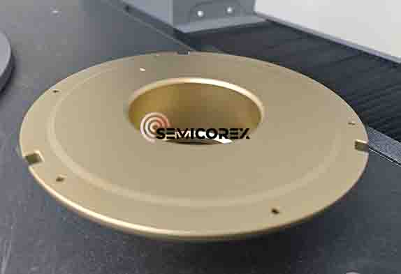
Most protective layers fail in aggressive atmospheres because they react slowly with the very gases they are meant to resist. Custom tantalum carbide coatings take a different route: the coating is adjusted to the furnace or reactor environment before it ever sees production. By tuning carbon-to-tantalum ratios, grain size, and layer density, the coating forms a tightly bonded barrier that resists hydrogen embrittlement, ammonia attack, and high-temperature oxidation far longer than off-the-shelf alternatives.
The practical gain shows up in runtime. In carburizing or halogen-rich atmospheres, a tailored TaC surface prevents both inward diffusion of process gases and outward migration of substrate impurities. That keeps wafer carriers, susceptors, and fixturing cleaner between cycles, reduces particle generation, and pushes preventive maintenance windows outward. The coating can also be applied selectively to high-wear edges and contact points, so dimensional stability holds even when thermal cycling is frequent.
Operators tend to notice the difference most during extended campaigns. Rather than replacing or recoating graphite components at fixed intervals, they can run through more cycles with less drift in temperature uniformity and fewer contamination-related scrap events. That kind of reliability comes less from a generic formula and more from matching the coating’s texture and thickness to the specific corrosive species, pressure range, and thermal profile of the chamber.
Matching Coating Architecture to Furnace Geometry
A coating sequence that performs well in one furnace often falls short in another simply because the chamber shape changes how heat and gas reach the substrate. Matching coating architecture to furnace geometry starts with reading the flow path: narrow annuli accelerate gas and sharpen deposition gradients, while wide chambers can create slow recirculation zones that deposit loosely bound material. Rather than copying a recipe, the layer stack should be adjusted to these local conditions.
Tall vertical furnaces, for example, rarely hold a uniform temperature from top to bottom, so a single thick barrier layer may crack if the lower zone runs cooler and develops higher residual stress. A better match uses a graded interlayer or a slightly thinner top coat in regions where thermal strain concentrates. In contrast, horizontal furnaces with side injection often favor a thicker edge build because the center of the load sees weaker precursor delivery.
Geometry also dictates where monitoring matters most. Corners, recesses, and downstream edges tend to be the first places where film thickness and adhesion drift outside specification. Coupons placed in these positions give a more honest picture than sampling only flat central surfaces. When the coating architecture is tuned to the furnace's actual thermal and flow field, the result is a more repeatable film that holds up across the entire working zone.
Thermal Stability Beyond 2000°C Without Sacrificing Uniformity
Most high-temperature materials face a familiar trade-off: push their limits beyond 2000°C and you often get uneven heat distribution, microstructural drift, or localized weak spots. This formulation approaches the problem differently. Instead of relying on a single phase that degrades under extreme thermal load, it uses a carefully balanced multi-component structure. The result is a material that holds its shape and performance even when the thermometer climbs past 2000°C, without the usual hot zones or unpredictable expansion patterns.
Uniformity here is not just about surface temperature. It extends to mechanical behavior, electrical properties, and dimensional stability across the entire sample. Laboratory testing with repeated thermal cycling shows less than 0.3% variation in key parameters between the center and the edge of test coupons. That consistency comes from engineered grain boundaries and controlled porosity, which allow heat to dissipate evenly instead of concentrating at flaws or interfaces.
For engineers working on next-generation furnaces, aerospace thermal shields, or high-performance sensors, this means fewer compromises. You no longer have to choose between surviving a 2000°C environment and maintaining reliable, uniform response throughout the part. The material simply does both, and it does so without requiring complex active cooling or exotic manufacturing steps.
Reducing Carbon Contamination in Sensitive Crystal Growth
Carbon contamination in sensitive crystal growth often originates from furnace components rather than the starting charge. Graphite heating elements, fibrous insulation, and even residues left by previous runs can release carbon-bearing species into the hot zone, where they dissolve into the melt or adsorb on the growing interface. The damage is rarely dramatic at first: a faint brown tint in an oxide crystal, a slight increase in optical absorption, or an unexpected shift in dopant segregation. For crystals used in laser, scintillator, or semiconductor applications, those subtle changes are enough to compromise performance.
One practical approach is to reduce the number of carbon-containing surfaces exposed to the growth atmosphere. Replacing graphite felt with dense alumina or zirconia insulation, lining susceptors with high-purity quartz, and switching to noble-metal crucibles where the chemistry allows all cut the available carbon at the source. Just as important is keeping the furnace interior clean. A short oxygen or ozone bake between runs can oxidize thin carbon films from heaters and shields, while a high-vacuum bake with a cold trap removes adsorbed hydrocarbons that would otherwise react during the next heating cycle.
For processes that cannot eliminate graphite entirely, separation and gas flow become the next line of defense. Sealing the crucible inside an inner growth chamber, purging with high-purity argon or nitrogen that has passed through a getter, and maintaining a slight overpressure near the melt all help carry carbon-bearing vapors away from the growth interface. Some growers also introduce a small amount of oxygen or water vapor to convert CO into CO2, which is less likely to dissolve in certain melts. The exact balance depends on the material, but the goal is the same: keep carbon at concentrations low enough that the crystal never knows the hot zone contained it.
Design and Rework Pathways That Keep Older Hardware Viable
Designers often treat a product launch as the finish line, but longevity comes from decisions made before the first unit ships. Sockets for processors, standard M.2 slots, swappable memory, and externally accessible batteries turn a sealed box into something a technician can actually service. When thermal pads and dust filters are easy to reach, the machine avoids the slow death of overheating and clogged fans. These are not premium flourishes; they are the difference between a device that lasts eight years and one that gets recycled after three.
Rework pathways matter just as much as initial assembly. Clear board labels, published schematics for legacy interfaces, and test points for voltage rails let independent repair shops diagnose failures without guessing. Some manufacturers now keep older firmware branches patched for security fixes long after the product is discontinued, which is far more useful than forcing users onto newer hardware. A ten-year-old industrial controller can stay in service if its communication protocol remains documented and its power supply uses a common footprint rather than a custom brick.
The supply chain also plays a role. When a vendor commits to stocking daughterboards, connectors, and displays for seven to ten years, refurbishers can source exact replacements instead of harvesting parts from dead units. Where official parts dry up, community-driven adapter boards and pin-compatible substitutes often appear, but only when the original design does not hide everything behind encryption and proprietary fasteners. Keeping older hardware viable, in the end, is less about heroic repair efforts and more about leaving the door open for them.
FAQ
Above roughly 1800°C, many coatings begin to react with process gases or lose mechanical adhesion. A TaC coating remains stable because its carbide bonds resist decomposition and it forms a dense surface that limits gas diffusion into the substrate.
SiC works well up to a point, but it can oxidize or react with ammonia and hydrogen mixtures under aggressive ramps. TaC offers better resistance to thermal shock and a lower tendency to generate particles once the process moves beyond typical SiC comfort zones.
The coating process can be adapted to pockets, recesses, and step features, but consistency depends on the source geometry and gas flow during deposition. Custom susceptors usually require some iterative fixturing to keep thickness uniform in tight corners.
High-purity graphite, C/C composites, and some refractory metals are common. Graphite remains the most widely used because its thermal expansion is close enough to TaC to avoid cracking over repeated thermal cycles.
The coating itself is quite thin, so the substrate and heater design still dominate the thermal profile. TaC contributes high emissivity and stable surface conditions, which help make temperature readings repeatable run after run, but it will not fix a poor base thermal design.
In inert or reducing environments, TaC can survive beyond 2000°C. In practice, the substrate and chamber hardware usually set the ceiling before the coating does, especially if any oxygen leaks in, because TaC oxidizes above 500-600°C.
Oxidizing species are the main threat. Halogen-containing plasmas can also etch TaC depending on temperature and bias. For most high-temperature nitride or carbide deposition chemistries using H2, NH3, or N2, it performs very well.
Typical checks include coating thickness mapping, adhesion testing, surface roughness before and after thermal cycling, and a particle performance benchmark in the tool. Some users also run a short production-matching process to verify there is no shift in film properties.
Conclusion
Graphite susceptors rarely fail because the base material loses mechanical strength; they fail because the working atmosphere attacks edges, gas channels, and loading pockets long before the bulk reaches its limits. A custom TaC coating changes that failure sequence by acting as a dense, chemically inert barrier against hydrogen, ammonia, silane, and metal-organic vapors, while also handling the thermal shock of repeated ramp cycles. The real difference shows up in how the coating is applied: thickness and grain orientation are tuned to the susceptor’s geometry rather than sprayed uniformly across every surface. That matters when you are trying to keep heat distribution even at the wafer or boule level.
Above 2000°C, many coatings go through recrystallization or microcracking that creates hot spots and uneven heat transfer. Custom TaC layers can be engineered with a gradient structure to hold their surface chemistry and emissivity stable long enough for extended production runs. In crystal growth processes where carbon contamination kills yield, the same coating also suppresses outgassing from the graphite underneath. Older furnace hardware benefits from this approach as well: worn susceptors can be stripped, rebuilt, and recoated with a revised architecture that accounts for the actual erosion pattern, making a replacement part unnecessary. That kind of rework path keeps mature equipment running without pretending every process chamber is identical.
Contact Us
Contact Person: Svenja Wei
Email: [email protected]
Tel/WhatsApp: +8613567891907
Website: https://www.semicorex.com